R88M-KE, R88D-KP
G5-series Pulse Train Input Type AC Servomotors/Servo Drives
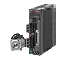
High-performance Servo Optimal for positioning Application.
Related Contents
- Features
- Lineup
- Specifications
- Dimensions
- Catalog / Manual / CAD / Software
last update: August 6, 2014
Servo Drive
General Specifications
| Item | Specifications | ||
|---|---|---|---|
| Ambient operating temperature and operating
humidity |
0 to +50°C, 20 to 85%RH max. (with no condensation) | ||
| Storage ambient temperature and humidity | -20 to +65°C, 20 to 85%RH. (with no condensation)
Maximum allowable temperature: 80°C for 72 hours maximum (with no condensation) |
||
| Operating and storage atmosphere | No corrosive gases | ||
| Vibration resistance | 10 to 60 Hz and at an acceleration of 5.88 m/s2 or less (Not to be run continuously at the resonance point) | ||
| Insulation resistance | Between power supply/power line terminals and FG terminal: 0.5 MΩ min. (at 500 VDC Megger) | ||
| Dielectric strength | Between power supply/power line terminals and FG terminal: 1,500 VAC for 1 min at 50/60 Hz | ||
| Protective structure | Built into panel | ||
| International
standard |
EC
directives |
EMC directive | EN55011, EN61000-6-2, IEC61800-3 |
| Low voltage
directive |
EN61800-5-1 | ||
| UL standards | UL508C | ||
| CSA standards | CSA22.2 No.14 | ||
Note: 1. The above items reflect individual evaluation testing. The results may differ under compound conditions.
Note: 2. Never perform dielectric strength or other megameter tests on the Servo Drive. Failure to follow this guideline may result in damaging the internal elements.
Note: 3. Depending on the operating conditions, some Servo Drive parts will require maintenance. For details, refer to the G5-series Pulse Train Input Type USER'S MANUAL. Man.No. I584
Characteristics
Servo Drives with 200VAC Input Power
for Single-phase/Three-phase input type
| Item | R88D-KP01H | R88D-KP02H | R88D-KP04H | R88D-KP08H | R88D-KP10H | R88D-KP15H | ||
|---|---|---|---|---|---|---|---|---|
| Continuous output current (rms) | 1.2A | 1.6A | 2.6A | 4.1A | 5.9A | 9.4A | ||
| Input power
supply |
Main circuit | Power supply
capacity |
0.5KVA | 0.5KVA | 0.9KVA | 1.3KVA | 1.8KVA | 2.3KVA |
| Power supply
voltage |
Single-phase or Three-phase 200 to 240 VAC (170 to 264 V) 50/60 Hz | |||||||
| Rated current | 1.6/0.9A *2 | 2.4/1.3A *2 | 4.1/2.4A *2 | 6.6/3.6A *2 | 9.1/5.2A *2 | 14.2/8.1A *2 | ||
| Heat value *1 | 14.3/13.7W *2 | 23/19W *2 | 33/24W *2 | 30/35.5W *2 | 57/49W *2 | 104/93W *2 | ||
| Control circuit | Power supply
voltage |
Single-phase 200 to 240 VAC (170 to 264 V) 50/60 Hz | ||||||
| Heat value *1 | 4W | 4W | 4W | 4W | 7W | 7W | ||
| Weight | Approx. 0.8 kg | Approx. 0.8kg | Approx. 1.0kg | Approx. 1.6kg | Approx. 1.8kg | Approx. 1.8kg | ||
| Maximum applicable motor capacity | 100W | 200W | 400W | 750W | 1kW | 1.5kW | ||
| Applicable
Servomotors |
3,000 r/min
Servomotors |
INC | KE05030H
KE10030H |
KE20030H | KE40030H | KE75030H | - | KE1K030H
KE1K530H |
| 2,000 r/min
Servomotors |
INC | - | - | - | - | KE1K020H | KE1K520H | |
| 1,000 r/min
Servomotors |
INC | - | - | - | - | - | KE90010H | |
*1. The heat value is given for rated operation.
*2. The first value is for single-phase input power and the second value is for 3-phase input power.
Servo Drives with 200VAC Input Power
for Three-phase input type
| Item | R88D-KP20H | R88D-KP30H | R88D-KP50H | ||
|---|---|---|---|---|---|
| Continuous output current (rms) | 13.4A | 18.7A | 33.0A | ||
| Input power
supply |
Main circuit | Power supply
capacity |
3.3KVA | 4.5KVA | 6.0KVA |
| Power supply
voltage |
Three-phase 200 to 230 VAC (170 to 253 V) 50/60 Hz | ||||
| Rated current | 11.8A | 15.1A | 21.6A | ||
| Heat value *1 | 139W | 108W | 328W | ||
| Control circuit | Power supply
voltage |
Single-phase 200 to 230 VAC (170 to 253 V) 50/60 Hz | |||
| Heat value *1 | 10W | 13W | 13W | ||
| Weight | Approx.2.7kg | Approx.4.8kg | Approx.4.8kg | ||
| Maximum applicable motor capacity | 2kW | 3kW | 5kW | ||
| Applicable
Servomotors |
3,000 r/min
Servomotors |
INC | KE2K030H | KE3K030H | KE4K030H
KE5K030H |
| 2,000 r/min
Servomotors |
INC | KE2K020H | KE3K020H | KE4K020H
KE5K020H |
|
| 1,000 r/min
Servomotors |
INC | - | KE2K010H | KE3K010H | |
*1. The heat value is given for rated operation.
Functions
Basic control
| Position control | Internally set speed control |
| Switching control |
Advanced control
| Vibration control | Gain switching | Friction torque compensation function |
| Adaptive filter | Torque limit | Inertia ratio switching function |
| Notch filter | Sequence I/O signal | Hybrid Vibration Suppression Function |
| Electronic gear function | Forward and reverse drive prohibition functions | Feed-forward function |
| Encoder dividing function | Disturbance observer function | Instantaneous speed observer function |
| Brake interlock | Gain switching 3 function |
Other functions
Realtime autotuning
Manual tuning
Various parameters
| Basic Parameters | Interface Monitor Setting Parameters |
| Gain Parameters | Extended Parameters |
| Vibration Suppression Parameters | Special Parameters |
| Analog Control Parameters |
AC Servomotors
General Specifications
| Item | 3,000-r/min motors | 2,000-r/min motors
3,000-r/min motors |
1,000-r/min motors | ||
|---|---|---|---|---|---|
| 50 to 750W | 1 to 5kW | 900 W to 3kW | |||
| Ambient operating temperature and
operating humidity |
0 to 40°C
20 to 85% RH (with no condensation) |
||||
| Storage ambient temperature and
humidity |
-20 to +65°C, 20% to 85% RH (with no condensation)
Maximum allowable temperature: 80°C for 72 hours maximum (standard humidity) |
||||
| Operating and storage atmosphere | No corrosive gases | ||||
| Vibration resistance * | Acceleration of 49 m/s2
24.5 m/s2 max. in X, Y, and Z directions when the motor is stopped |
||||
| Impact resistance | Acceleration of 98 m/s2 max. 3 times each in X, Y, and Z directions | ||||
| Insulation resistance | Between power terminal and FG terminal: 20 MΩ min. (at 500 VDC Megger) | ||||
| Dielectric strength | 1,500 VAC between power terminal and FG terminal for 1 min (voltage 200 V)
1,000 VAC between brake terminal and FG terminal for 1 min |
||||
| Insulation class | Type B | Type F | |||
| Protective structure | IP65 (except for through-shaft parts and motor and encoder connector pins) | ||||
| International
standard |
EC
directive |
Low voltage
directive |
EN60034-1/-5 | ||
| UL standards | UL1004-1 | ||||
| CSA standards | CSA 22.2 No.100 | ||||
* The amplitude may be amplified by machine resonance. Do not exceed 80% of the specified value for extended periods of time.
Note: 1. Do not use the cable when it is laying in oil or water.
Note: 2. Do not expose the cable outlet or connections to stress due to bending or the weight of the cable itself.
Characteristics
Characteristics 3,000 r/min Servomotors (200 VAC Input Power)
50~750W
| Model (R88M-)
|
KE05030H | KE10030H | KE20030H | KE40030H | KE75030H | ||
|---|---|---|---|---|---|---|---|
| Item | Unit | ||||||
| Rated output*1 | W | 50 | 100 | 200 | 400 | 750 | |
| Rated torque*1 | N • m | 0.16 | 0.32 | 0.64 | 1.3 | 2.4 | |
| Rated rotation speed | r/min | 3000 | |||||
| Momentary maximum rotation speed | r/min | 5000 | 4500 | ||||
| Momentary maximum torque*1 | N • m | 0.48 | 0.95 | 1.91 | 3.8 | 7.1 | |
| Rated current*1 | A (rms) | 1.1 | 1.1 | 1.6 | 2.6 | 4 | |
| Momentary maximum current*1 | A (rms) | 4.7 | 4.7 | 6.9 | 11 | 17 | |
| Rotor inertia | Without brake | kg • m2 | 0.025×10⁻⁴ | 0.051×10⁻⁴ | 0.14×10⁻⁴ | 0.26×10⁻⁴ | 0.87×10⁻⁴ |
| With brake | kg • m2 | 0.027×10⁻⁴ | 0.054×10⁻⁴ | 0.16×10⁻⁴ | 0.28×10⁻⁴ | 0.97×10⁻⁴ | |
| Applicable load inertia | - | 30 times the rotor inertia max. *2 | 20 times
the rotor inertia max. *2 |
||||
| Torque constant *1 | N • m/A | 0.10±10% | 0.21±10% | 0.29±10% | 0.36±10% | 0.45±10% | |
| Power rate *1 | Without brake | kW/s | 10.4 | 20.1 | 30.3 | 62.5 | 66 |
| With brake | kW/s | 9.3 | 19 | 25.8 | 57.2 | 58.9 | |
| Mechanical
time constant |
Without
brake |
ms | 1.56 | 1.08 | 0.71 | 0.52 | 0.45 |
| With brake | ms | 1.74 | 1.14 | 0.84 | 0.57 | 0.51 | |
| Electrical time constant | ms | 0.7 | 0.79 | 2.6 | 3 | 4.6 | |
| Allowable radial load *3 | N | 68.6 | 68.6 | 245 | 245 | 392 | |
| Allowable thrust load *3 | N | 58.8 | 58.8 | 98 | 98 | 147 | |
| Weight | Without
brake |
kg | Approx.
0.32 |
Approx.
0.47 |
Approx.
0.82 |
Approx.
1.2 |
Approx.
2.3 |
| With brake | kg | Approx.
0.32 |
Approx.
0.68 |
Approx.
1.3 |
Approx.
1.7 |
Approx.
3.1 |
|
| Radiator plate dimensions
(material) |
100×80×t10 (AI) | 130×120×t12 (AI) | 170×160
×t12 (AI) |
||||
| Applicable drivers (R88D-) | KP01H | KP01H | KP02H | KP04H | KP08H | ||
| Brake
specifications |
Brake inertia | kg • m2 | 2×10⁻⁷ | 2×10⁻⁷ | 1.8×10⁻⁶ | 1.8×10⁻⁶ | 7.5×10⁻⁶ |
| Excitation voltage *4 | V | 24 VDC±5% | |||||
| Power consumption
(at 20°C) |
W | 7 | 7 | 9 | 9 | 10 | |
| Current consumption (at
20°C) |
A | 0.3 | 0.3 | 0.36 | 0.36 | 0.42 | |
| Static friction torque | N • m | 0.29 min. | 0.29 min. | 1.27 min. | 1.27 min. | 2.45min. | |
| Attraction time *5 | ms | 35 max. | 35 max. | 50 max. | 50 max. | 70max. | |
| Release time *5 | ms | 20 max. | 20 max. | 15 max. | 15 max. | 20max.*6 | |
| Backlash | ±1° | ||||||
| Allowable work per braking | J | 39.2 | 39.2 | 137 | 137 | 196 | |
| Allowable total work | J | 4.9×10³ | 4.9×10³ | 44.1×10³ | 44.1×10³ | 1.47×10⁵ | |
| Allowable angular
acceleration |
rad/s2 | 30,000 max. (Speed of 2,800 r/min or more
must not be changed in less than 10 ms) |
10000 | ||||
| Brake limit | - | 10 million times min. | |||||
| Rating | - | Continuous | |||||
| Insulation class | - | Type F | |||||
1000~5000W
| Model (R88M-)
|
KE1K030H | KE1K530H | KE2K030H | KE3K030H | KE4K030H | KE5K030H | ||
|---|---|---|---|---|---|---|---|---|
| Item | Unit | |||||||
| Rated output*1 | W | 1000 | 1500 | 2000 | 3000 | 4000 | 5000 | |
| Rated torque*1 | N • m | 3.18 | 4.77 | 6.37 | 9.55 | 12.7 | 15.9 | |
| Rated rotation speed | r/min | 3000 | ||||||
| Momentary maximum rotation speed | r/min | 5000 | 4500 | |||||
| Momentary maximum torque*1 | N • m | 9.55 | 14.3 | 19.1 | 28.6 | 38.2 | 47.7 | |
| Rated current*1 | A (rms) | 6.6 | 8.2 | 11.3 | 18.1 | 19.6 | 24 | |
| Momentary maximum current*1 | A (rms) | 28 | 35 | 48 | 77 | 83 | 102 | |
| Rotor inertia | Without brake | kg • m2 | 2.03×10⁻⁴ | 2.84×10⁻⁴ | 3.68×10⁻⁴ | 6.50×10⁻⁴ | 12.9×10⁻⁴ | 17.4×10⁻⁴ |
| With brake | kg • m2 | 2.35×10⁻⁴ | 3.17×10⁻⁴ | 4.01×10⁻⁴ | 7.85×10⁻⁴ | 14.2×10⁻⁴ | 18.6×10⁻⁴ | |
| Applicable load inertia | - | 15 times the rotor inertia max. *2 | ||||||
| Torque constant *1 | N • m/A | 0.37 | 0.45 | 0.44 | 0.41 | 0.49 | 0.49 | |
| Power rate *1 | Without brake | kW/s | 49.8 | 80.1 | 110 | 140 | 126 | 146 |
| With brake | kW/s | 43 | 71.8 | 101 | 116 | 114 | 136 | |
| Mechanical
time constant |
Without
brake |
ms | 0.61 | 0.49 | 0.44 | 0.41 | 0.51 | 0.5 |
| With brake | ms | 0.71 | 0.55 | 0.48 | 0.49 | 0.56 | 0.54 | |
| Electrical time constant | ms | 5.8 | 6.3 | 6.7 | 11 | 12 | 13 | |
| Allowable radial load *3 | N | 490 | 490 | 490 | 490 | 784 | 784 | |
| Allowable thrust load *3 | N | 196 | 196 | 196 | 196 | 343 | 343 | |
| Weight | Without
brake |
kg | Approx.
3.5 |
Approx.
4.4 |
Approx.
5.3 |
Approx.
8.3 |
Approx.
11.0 |
Approx.
14.0 |
| With brake | kg | Approx.
4.5 |
Approx.
5.4 |
Approx.
6.3 |
Approx.
9.4 |
Approx.
12.6 |
Approx.
16.0 |
|
| Radiator plate dimensions
(material) |
320×300×t20 (AI) | 380×350×t30 (AI) | ||||||
| Applicable drivers (R88D-) | KP15H | KP15H | KP20H | KP30H | KP50H | KP50H | ||
| Brake
specifications |
Brake inertia | kg • m2 | 0.33×10⁻⁴ | 0.33×10⁻⁴ | 0.33×10⁻⁴ | 0.33×10⁻⁴ | 1.35×10⁻⁴ | 1.35×10⁻⁴ |
| Excitation voltage *4 | V | 24 VDC±10% | ||||||
| Power consumption
(at 20°C) |
W | 19 | 19 | 19 | 19 | 22 | 22 | |
| Current consumption (at
20°C) |
A | 0.81±10% | 0.81±10% | 0.81±10% | 0.81±10% | 0.90±10% | 0.90±10% | |
| Static friction torque | N • m | 7.8min. | 7.8min. | 7.8min. | 11.8min. | 16.1min. | 16.1min. | |
| Attraction time *5 | ms | 50max. | 50max. | 50max. | 80max. | 110max. | 110max. | |
| Release time *5 | ms | 15max.*6 | 15max.*6 | 15max.*6 | 15max.*6 | 50max.*7 | 50max.*7 | |
| Backlash | ±1° | |||||||
| Allowable work per braking | J | 392 | 392 | 392 | 392 | 1470 | 1470 | |
| Allowable total work | J | 4.9×10⁵ | 4.9×10⁵ | 4.9×10⁶ | 4.9×10⁶ | 2.2×10⁶ | 2.2×10⁶ | |
| Allowable angular
acceleration |
rad/s2 | 10000 | ||||||
| Brake limit | - | 10 million times min. | ||||||
| Rating | - | Continuous | ||||||
| Insulation class | - | Type F | ||||||
Characteristics 2,000 r/min Servomotors (200 VAC Input Power)
| Model (R88M-)
|
KE1K020H | KE1K520H | KE2K020H | KE3K020H | KE4K020H | KE5K020H | ||
|---|---|---|---|---|---|---|---|---|
| Item | Unit | |||||||
| Rated output *1 | W | 1000 | 1500 | 2000 | 3000 | 4000 | 5000 | |
| Rated torque *1 | N • m | 4.77 | 7.16 | 9.55 | 14.3 | 19.1 | 23.9 | |
| Rated rotation speed | r/min | 2000 | ||||||
| Momentary maximum rotation speed | r/min | 3000 | ||||||
| Momentary maximum torque*1 | N • m | 14.3 | 21.5 | 28.6 | 43 | 57.3 | 71.6 | |
| Rated current *1 | A (rms) | 5.7 | 9.4 | 11.5 | 17.4 | 21 | 25.9 | |
| Momentary maximum current*1 | A (rms) | 24 | 40 | 49 | 74 | 89 | 110 | |
| Rotor inertia | Without brake | kg • m2 | 4.60×10⁻⁴ | 6.70×10⁻⁴ | 8.72×10⁻⁴ | 12.9×10⁻⁴ | 37.6×10⁻⁴ | 48.0×10⁻⁴ |
| With brake | kg • m2 | 5.90×10⁻⁴ | 7.99×10⁻⁴ | 10.0×10⁻⁴ | 14.2×10⁻⁴ | 38.6×10⁻⁴ | 48.8×10⁻⁴ | |
| Applicable load inertia | - | 10 times the rotor inertia max. *2 | ||||||
| Torque constant *1 | N • m/A | 0.63 | 0.58 | 0.64 | 0.59 | 0.7 | 0.7 | |
| Power rate*1 | Without brake | kW/s | 49.5 | 76.5 | 105 | 159 | 97.1 | 119 |
| With brake | kW/s | 38.6 | 64.2 | 91.2 | 144 | 94.5 | 117 | |
| Mechanical
time constant |
Without
brake |
ms | 0.8 | 0.66 | 0.66 | 0.57 | 0.65 | 0.63 |
| With brake | ms | 1.02 | 0.8 | 0.76 | 0.63 | 0.66 | 0.64 | |
| Electrical time constant | ms | 9.4 | 10 | 10 | 12 | 20 | 19 | |
| Allowable radial load *3 | N | 490 | 490 | 490 | 784 | 784 | 784 | |
| Allowable thrust load *3 | N | 196 | 196 | 196 | 343 | 343 | 343 | |
| Weight | Without
brake |
kg | Approx.5.2 | Approx.6.7 | Approx.8.0 | Approx.11.0 | Approx.15.5 | Approx.18.6 |
| With brake | kg | Approx.6.7 | Approx.8.2 | Approx.9.5 | Approx.12.6 | Approx.18.7 | Approx.21.8 | |
| Radiator plate dimensions
(material) |
275×260×t15 (AI) | 380×350×t30 (AI) | 470×440×t30 (AI) | |||||
| Applicable drivers (R88D-) | KP10H | KP15H | KP20H | KP30H | KP50H | KP50H | ||
| Brake
specifications |
Brake inertia | kg • m2 | 1.35×10⁻⁴ | 1.35×10⁻⁴ | 1.35×10⁻⁴ | 1.35×10⁻⁴ | 4.7×10⁻⁴ | 4.7×10⁻⁴ |
| Excitation voltage *4 | V | DC24V±10% | ||||||
| Power consumption
(at 20°C) |
W | 14 | 19 | 19 | 22 | 31 | 31 | |
| Current consumption (at
20°C) |
A | 0.59±10% | 0.79±10% | 0.79±10% | 0.90±10% | 1.3±10% | 1.3±10% | |
| Static friction torque | N • m | 4.9min. | 13.7min. | 13.7min. | 16.2min. | 24.5min. | 24.5min. | |
| Attraction time *5 | ms | 80max. | 100max. | 100max. | 110max. | 80max. | 80max. | |
| Release time *5 | ms | 70max. *6 | 50max. *6 | 50max. *6 | 50max. *6 | 25max. *7 | 25max. *7 | |
| Backlash | ±1° | |||||||
| Allowable work per braking | J | 588 | 1176 | 1176 | 1470 | 1372 | 1372 | |
| Allowable total work | J | 7.8×10⁵ | 1.5×10⁶ | 1.5×10⁶ | 2.2×10⁶ | 2.9×10⁶ | 2.9×10⁶ | |
| Allowable angular
acceleration |
rad/s2 | 10000 | ||||||
| Brake limit | - | 10 million times min. | ||||||
| Rating | - | Continuous | ||||||
| Insulation class | - | Type F | ||||||
Characteristics 1,000 r/min Servomotors (200 VAC Input Power)
| Model (R88M-)
|
KE90010H | KE2K010H | KE3K010H | ||
|---|---|---|---|---|---|
| Item | Unit | ||||
| Rated output *1 | W | 900 | 2000 | 3000 | |
| Rated torque *1 | N • m | 8.59 | 19.1 | 28.7 | |
| Rated rotation speed | r/min | 1000 | |||
| Momentary maximum rotation speed | r/min | 2000 | |||
| Momentary maximum torque*1 | N • m | 19.3 | 47.7 | 71.7 | |
| Rated current *1 | A (rms) | 7.6 | 17 | 22.6 | |
| Momentary maximum current*1 | A (rms) | 24 | 60 | 80 | |
| Rotor inertia | Without brake | kg • m2 | 6.70×10⁻⁴ | 30.3×10⁻⁴ | 48.4×10⁻⁴ |
| With brake | kg • m2 | 7.99×10⁻⁴ | 31.4×10⁻⁴ | 49.2×10⁻⁴ | |
| Applicable load inertia | - | 10 times the rotor inertia max. *2 | |||
| Torque constant *1 | N • m/A | 0.86 | 0.88 | 0.96 | |
| Power rate *1 | Without brake | kW/s | 110 | 120 | 170 |
| With brake | kW/s | 92.4 | 116 | 167 | |
| Mechanical time constant | Without brake | ms | 0.66 | 0.75 | 0.63 |
| With brake | ms | 0.78 | 0.78 | 0.64 | |
| Electrical time constant | ms | 11 | 18 | 21 | |
| Allowable radial load *3 | N | 686 | 1176 | 1470 | |
| Allowable thrust load *3 | N | 196 | 490 | 490 | |
| Weight | Without brake | kg | Approx.6.7 | Approx.14.0 | Approx.20.0 |
| With brake | kg | Approx.8.2 | Approx.17.5 | Approx.23.5 | |
| Radiator plate dimensions (material) | 270×260×t15 (AI) | ||||
| Applicable drivers (R88D-) | KP15H | KP30H | KP50H | ||
| Brake specifications | Brake inertia | kg • m2 | 1.35×10⁻⁴ | 4.7×10⁻⁴ | 4.7×10⁻⁴ |
| Excitation voltage *4 | V | DC24V±10 | |||
| Power consumption (at 20°C) | W | 19 | 31 | 34 | |
| Current consumption (at 20°C) | A | 0.79±10% | 1.3±10% | 1.4±10% | |
| Static friction torque | N • m | 13.7min. | 24.5min. | 58.8min. | |
| Attraction time *5 | ms | 100max. | 80max. | 150max. | |
| Release time *5 | ms | 50max. *6 | 25max. *7 | 50max. *7 | |
| Backlash | ±1° | ||||
| Allowable work per braking | J | 1176 | 1372 | 1372 | |
| Allowable total work | J | 1.5×10 6 | 2.9×10⁶ | 2.9×10⁶ | |
| Allowable angular acceleration | rad/s2 | 10000 | |||
| Brake limit | - | 10 million times min. | |||
| Rating | - | Continuous | |||
| Insulation class | - | Type F | |||
*1. These are the values when the motor is combined with a driver at normal temperature (20°C, 65%). The momentary maximum torque indicatesthe standard value.
*2. Applicable load inertia.
• The operable load inertia ratio (load inertia/rotor inertia) depends on the mechanical configuration and its rigidity. For a machine with high rigidity, operation is possible even with high load inertia. Select an appropriate motor and confirm that operation is possible.
• If the dynamic brake is activated frequently with high load inertia, the Dynamic Brake Resistor may burn. Do not repeatedly turn the servo ON/ OFF while the dynamic brake is enabled.
• The dynamic brake is designed only for emergency stops. Design the system so that the Servomotor remains stopped for at least 3 minutes after applying the dynamic brake. Otherwise the dynamic brake circuits may fail.
*3. The allowable radial and thrust loads are the values determined for a limit of 20,000 hours at normal operating temperatures. The allowableradial loads are applied as shown in the following diagram.
*4. This is a non-excitation brake. (It is released when excitation voltage is applied.)
*5. The operation time is the value (reference value) measured with a surge suppressor (CR50500 by Okaya Electric Industries Co., Ltd.).
*6. Direct current switching with a varistor (Z15D151 by Ishizuka Electronics Co.).
*7. Direct current switching with a varistor (TNR9G820K by Nippon Chemi-Con Corporation).
Encoder Specifications
Incremental Encoders
| Item | Specifications |
|---|---|
| Encoder system | Optical encoder |
| 20 bits | |
| No. of output pulses | Phases A and B: 262,144 pulses/rotation
Phase Z: 1 pulse/rotation |
| Power supply voltage | 5 VDC±5% |
| Power supply current | 180 mA (max.) |
| Output signals | +S, -S |
| Output interface | RS-485 compliance |
last update: August 6, 2014