MD Series
Autonomous Mobile Robots
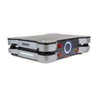
A mobile robot for heavy-duty transport up to 900 kg. Self-mapping and safe autonomous navigation. Available in 650 kg and 900 kg models.
Related Contents
- Features
- Lineup
- Specifications
- Dimensions
- Catalog / Manual / CAD / Software
last update: October 1, 2025
| Item | Details | ||
|---|---|---|---|
| Model | MD-650 | MD-900 | |
| Weight (no battery or accessories) | 220 kg | ||
|
Envi-
ronment |
Ambient Temperature | 5 to 40°C | |
| Storage Temperature | -20 to 60°C | ||
| Ambient Humidity | 5% to 95% (non-condensing) | ||
| Operating Environment | Indoor usage only, no corrosive or explosive gas or liquid | ||
| Dust / Smoke | Accumulated dust smaller than 37 μm cannot exceed 1.5 mL / m2 in the
operating environment. Avoid operating in areas with smoke. |
||
| Altitude | 2000 m maximum | ||
| Pollution Degree | 2 | ||
| Ingress Protection Class *1 | IP22 (IP10 for charging pads) | ||
| Enclosure Rating | Type 2 | ||
| Atmospheric | Non-hazardous environments (no explosive gas and oil mist). | ||
| Cleanroom Rating *2 | ISO 4 / Class 10 | ||
|
Floor
Conditions |
Floor Requirements | No water, oil, or dirt | |
| Minimum Floor Flatness | FF25 (ACI 117 standard) | ||
| Minimum Floor Levelness | FL25 (ACI 117 standard) | ||
|
Maximum Step Traversal
(speed limited *3) |
10 mm / 15 mm | ||
| Maximum Gap Traversal *4 | 20 mm / 30 mm | ||
| Maximum Slope | Max. 5° / 8.75% incline | ||
|
Minimum Floor
Compressive Strength |
7.2 MPa | 9.4 MPa | |
|
Minimum Coefficient of
Friction |
Flat surfaces: 0,6; Inclined surfaces: 0.8 | ||
| Navigation | Routing | Autonomous routing by localizing with Safety Laser Scanners, based on
environment mapping. |
|
|
Environmental Map-
Making Method |
Scan by driving the AMR through the environment and uploading the scan
data to the MobilePlanner. |
||
| Low Lasers | Two Low Lasers are provided to detect obstacles below the scanning plane
of the Safety Laser Scanners. |
||
|
Supplementary Laser
Scanners (Optional) |
Two optional, Supplementary Laser Scanners can be added for object
detection in the vertical plane |
||
| Visual Indicators | Light discs are located on the sides of the AMR. Light strips are located on
the front and back of the AMR. Additional indicators can be added. |
||
| Maximum Payload Capacity | 650 kg | 900 kg | |
| Mobility | Run Time *5 | 10 h (no payload); 8 h (full payload) | |
| Swing Radius | 729 mm | ||
| Turn Radius | 0 mm | ||
|
Maximum Translational
Speed (forward and reverse) |
2200 mm/s | 1800 mm/s | |
|
Maximum Translational
Acceleration |
900 mm/s2 | ||
|
Maximum Translational
Deceleration |
1300 mm/s2 | ||
|
Maximum Rotational
Speed *6 |
60 °/s | ||
|
Maximum Rotational
Acceleration |
100 °/s2 | ||
|
Maximum Rotational
Deceleration |
150 °/s2 | ||
|
Maximum Moment of
Inertia |
250 kg-m2 | 300 kg-m2 | |
|
Stop Position Repeatability
(Single AMR) *7 |
To a position: ±55 mm, ±2°
To standard target: ±25 mm, ±2° With HAPS: ±8 mm, ±0.5° With CAPS: ±4 mm, ±0.4° |
||
|
Stop Position Repeatability
(Fleet) *7 |
To a position: ±75 mm, ±2°
To standard target: ±35 mm, ±2° With HAPS: ±10 mm, ±0.5° With CAPS: ±16 mm, ±0.5° |
||
|
Drive
Wheels |
Materials | Steel wheels with ESD tread | |
|
Passive
Casters |
Materials | Cast iron wheels with polyurethane tread | |
|
Auxiliary
Power |
Unregulated | 40 to 57 VDC (51.2 VDC nominal); 40 A fused | |
| Regulated | 23 to 25 VDC; 0.7 A fused | ||
| Standards | AMR | EN ISO 12100, EN ISO 13849-1, EN 60204-1, EN ISO 10218-1,
EN 61326-3-1, EN 61326-1, EN 12895, EN ISO 3691-4, CAN/UL 3100, CAN/CSA-Z434, KS C 9610-6-2, KS C 9610-6-4, ANSI RIA 15.08 |
|
| Battery | ANSI/CAN/UL/ULC 2271, UN 38.3 | ||
| Charging Station | EN 61204-7, EN 62477-1, UL1012, CAN/CSA C22.2.107.2 | ||
| Wireless | IEEE 802.11 a/b/g | ||
|
Certification
Markings |
Battery | cTUVus, CE | |
|
Power Supply Box and
Docking Target |
cTUVus | ||
|
Signal
Interfaces |
Wireless | Fleet communication and other maintenance functions | |
| RJ-45 Ports | Four ports for connections to internal devices | ||
| Digital I/O | Eight PNP / sourcing inputs; Eight PNP / sourcing outputs | ||
| Safety | Emergency stop and protective signals, alternate safety zone switching, and
no-motion output |
||
| Lights | Connects user-supplied visual signal devices | ||
| Buzzer | Connects user-supplied audible signal devices | ||
|
Safety
Features |
Safety Laser Scanners | Two Safety Laser Scanners are included to provide a 360° detection area
around the AMR. The scanning plane is positioned 175 mm above the floor. Lasers are rated as Class 1M, eye-safe, per IEC 60825-1 and 21 CFR 1040.10 and 1040.11. |
|
|
Safety Laser Scanner
Zone Sets |
A pair of safety-rated alternate safety zone inputs can toggle the Safety Laser
Scanner zones between a default configuration or an alternate configuration. |
||
| E-STOP Buttons | Five E-STOP buttons are located on the AMR (sides and Operator Panel).
Additional E-STOP buttons can be added to the payload structure. |
||
| Audible Indicators | Two speakers are included. Additional buzzers can be added. | ||
| Emergency Stop | Stops the AMR and requires user intervention to resume operation. | ||
| Protective Stop | Stops the AMR temporarily and automatically resumes operation when
safety conditions are met. |
||
|
Operator
Panel |
Display | 127 mm diagonal LCD | |
| Controls | • E-STOP button
• ON/OFF buttons • Brake release button • Pendant port • Keyed Mode Selection Switch |
||
*1. The supplied Top Plate Plugs must be inserted to achieve an IP22 rating.
*2. Cleanroom ratings are associated with the AMR and charging components when used together as a complete system.
*3. Traversing a 10 mm step must occur at speeds below 500 mm/s in the forward direction and 400 mm/s in the reverse direction. Traversing a 15 mm step must occur at speeds below 300 mm/s in the forward and reverse directions. Frequent driving over steps will shorten the lifespan of the drivetrain components. Steps should have smooth, rounded profiles.
*4. 20 mm gaps may be traversed at any speed. Traversing a 30 mm gap must occur at speeds below 2000 mm/s for MD-650 and speeds below 1500 mm/s for MD-900. Frequent driving over gaps will shorten the lifespan of the drivetrain components.
*5. Auxiliary power draw will impact these times.
*6. The maximum rotational speed is reduced to 45 degrees/s when the AMR is traveling at speeds over 100 mm/s.
*7. Stop position repeatability values were obtained using default AMR parameters and a map created by the MD-series AMR.
MobilePlanner Software Requirements
| MobilePlanner, PC | Operating System | Windows 10 (64-bit version), Windows 11 |
|---|---|---|
| CPU | 1.5 GHz dual-core CPU recommended | |
| Main Memory | 1.5 GB min. (4 GB min. recommended) | |
| Hard Disk | At least 200 MB of available space | |
| Video Memory | 256 MB min. | |
| Display | XGA 1280 x 720, 16 million colors minimum | |
|
MobilePlanner,
Tablet Edition |
Operating System | Android® OS, Version 9 or newer, minimum 2 GB of RAM |
| iOS®, Version 10 or newer | ||
| Supported Languages | English, German, Japanese, French, Italian, Korean, Spanish, Polish,
Simplified Chinese and Traditional Chinese. |
|
Virtual Fleet Manager Software Minimum Hardware Requirements
| Fleet Size / AMR Count | Small / ≤ 5 | Medium ≤ 15 | Large ≤ 30 | X-Large > 30 *1 |
|---|---|---|---|---|
| Virtual CPU | 2 cores | 4 cores | ||
| Clockspeed | 4GHz | 8 GHz | 12 GHz | 16 GHz |
| Virtual RAM | 8 GB | 16 GB | 24 GB | 32 GB |
| Virtual Disk | 512 GB | 1 TB | ||
| FLOW software version | Minimum FLOW Core 4.0 | |||
*1. Contact your local OMRON representative for fleets larger than 100.
Note: The PC/IPC/Server is supplied by the user.
Charging Station
| Maximum Current | Input current: 25 A
Output current: 120 A (nominal) *1 |
|---|---|
| Input Voltage | 3-phase
200 to 240 VAC, 50/60 Hz (Delta/Wye) 380 to 415 VAC, 50/60 Hz (Wye only) |
| Output voltage | 40 to 57 VDC |
| Power Consumption | 7.75 kW |
| Maximum Power Output | 6.84 kW |
| Humidity | 5% to 95%, non-condensing |
| Ambient Operating Temperature | 5 to 40°C |
| Storage Temperature | -20 to 60°C |
| Ingress Protection | IP20 (IP10 for charging pads) |
| Cleanroom Rating *2 | ISO 4 / Class 10 |
| Altitude | 2000 m maximum |
| Pollution degree | 2 |
| Equipment Class | 1 |
| Weight | Power Supply Box: 111 kg
Docking Target: 28 kg |
| Docking Target Mounting | To floor and/or wall |
*1. Fused at 150 A
*2. Cleanroom ratings are associated with the AMR and charging components when used together as a complete system.
High Accuracy Positioning System
| Ingress Protection | IP64 | |
|---|---|---|
| Environment | -40 to 85°C | |
| Magnetic Tape | Width | 25 mm |
| Orientation | South up | |
|
Markers
(Magnetic Tape) |
Width | 25 mm |
| Length | 250 mm min. for 500 mm/s drive speed | |
| Orientation | North up | |
| Separation from Tape | 20 to 30 mm | |
| Protective Covering Tape (recommended) | Mighty Line Safety Floor Tape, Solid (102 mm width) | |
Pendant
| Ambient Operating Temperature | 0 to 40°C |
|---|---|
| Storage Temperature | -20 to 65°C |
| Humidity | 5% to 95%, non-condensing |
| Altitude | 2000 m |
| Ingress Protection Class | IP30 |
Battery
| Type | Lithium-Ion (LiFePO4) |
|---|---|
| Voltage | 40 to 57 VDC (51.2 VDC nominal) |
| Capacity | 38 Ah nominal |
| Energy | 2048 Wh nominal |
| Recharge Time | 19.6 minutes (from 20% to 80%) *1 |
| Charge Cycles | Approximately 3000 cycles *2 *3 |
| Charging Method | Automatic or manual |
| Ambient Operating Temperature | 5 to 40°C |
| Storage Temperature | < 1 month: -20 to 45°C
< 3 months: -20 to 35°C > 3 months: 20 to 25°C |
| Humidity (Storage) | 65% or less |
| Humidity (Operation) | 5% to 95%, non-condensing |
| Altitude | 4500 m, operating
15240 m, transporting |
| Ingress Protection Class | IP33 |
| Weight | 29 kg |
*1. Charging time can vary based on battery cell temperature and state of charge.
*2. Approximately 80% of nominal battery capacity will be available after using the battery at 100% depth of discharge.
*3. Under manufacturer's test conditions of 25°C ±3°, 25% to 85% relative humidity, 40 A charge/discharge, 57 and 40 VDC charge/discharge, with 60 minutes of inactivity after charging/discharging. Actual cycles may vary according to the application.
last update: October 1, 2025