K7GE-MG
Insulation Resistance Monitoring Device
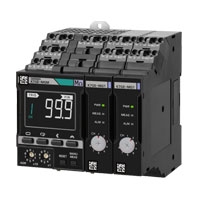
Reliable, Safe and Accurate Automatic Insulation Resistance Measurements
Related Contents
- Features
- Lineup
- Specifications
- Dimensions
- Catalog / Manual / CAD / Software
last update: April 1, 2021
Ratings and Specifications
| Item | Specifications | |
|---|---|---|
| Power supply voltage
and frequency |
K7GE-MGMA: 100 to 240 VAC, 50/60 Hz
K7GE-MGMD: 24 VAC, 50/60 Hz, 24 VDC |
|
| Operating voltage range | 85% to 110% of the rated voltage | |
| Operating frequency
range |
45 to 65 Hz | |
| Power consumption | Maximum Unit configuration: one Main Unit and eight Probe Units
12.9 VA max. (100 to 240 VAC)/7.8 VA max. (24 VAC)/4.7 W max. (24 VDC) Minimum Unit configuration: one Main Unit and one Probe Unit 8.4 VA max. (100 to 240 VAC)/4.6 VA max. (24 VAC)/2.5 W max. (24 VDC) |
|
| Ambient operating
temperature |
-10 to 55°C (with no condensation or icing) | |
| Ambient operating
humidity |
25% to 85% (with no condensation) | |
| Storage temperature | -20 to 65°C | |
| Altitude | 2,000 m max. | |
| Recommended fuse | T2A, time delay, high-breaking capacity (for Main Unit operating power supply)
Tripping current: 7 A max., fast-blow (for Probe Unit voltage input) |
|
| Insulation resistance | 20 MΩ min.
Between all external terminals and the case, between all power supply terminals and all other terminals, between PE terminal, and trigger input terminal, all communications terminals and all transistor output terminals 1,000 MΩ min. Between Probe Unit voltage monitoring terminal and PE terminal |
|
| Dielectric strength | 2,000 VAC for 1 minute
Between all external terminals and the case, between all power supply terminals and all other terminals, between PE terminal, and trigger input terminal, all communications terminals and all transistor output terminals 1,000 VDC for 1 minute Between Probe Unit voltage monitoring terminal and PE terminal |
|
| Vibration resistance | Frequency: 10 to 55 Hz, 0.35-mm single amplitude, acceleration 50 m/s2,
10 sweeps of 5 min each in X, Y, and Z directions |
|
| Shock resistance | 100 m/s2, 3 times each in X, Y, and Z axes, 6 directions | |
| Degree of protection | IP20 | |
| Terminal block type | Push-In Plus | |
| Exterior color | Black (Munsell N 1.5) | |
| Mounting | DIN Track mounting | |
| Weight | Main Unit: Approx. 156 g
Probe Unit: Approx. 63 g |
|
| Installation environment | Operation power supply: EN/IEC 61010-1 Over-voltage category II Pollution degree 2
Measurement circuit: EN/IEC 61010-2-030 Pollution degree 2 For details about the measurement category, refer to Cataloge. |
|
| Electromagnetic
environment |
EN/IEC 61326-1 Industrial electromagnetic environment | |
| Safety standards | UL 61010-1, CAN/CSA-C22.2 No.61010-1
Korean Radio Waves Act (KN 61000-6-2 and KN 11) RCM |
|
| Wiring
material |
Wire type | Solid wire or stranded wire |
| Wiring material | Copper | |
| Recommended
wire |
0.25 to 1.5 mm2
AWG 24 to AWG 16 |
|
| Stripping length
Without ferrules |
8 mm | |
Measurement Specifications
| Item | Specifications |
|---|---|
| Measurement range | 0.1 to 99.9 MΩ (0.0 MΩ for less than 0.1 MΩ) |
| Measuring accuracy | ±5% rdg. ±1 digit
(at ambient temperature -10 to 55°C and ambient humidity 25% to 65%) |
| Megger voltage | 50 VDC |
| Measurement operation | Perform one measurement operation for each trigger. One-shot trigger. |
| Average count | Disabled (1 time)/Enabled (8 times) |
| Measurement target | Single-phase/3-phase AC induction motors
An inverter-driven motor requires a contactor on the secondary coil of the inverter. Similarly, a servo motor requires a contactor on the secondary coil of the Servo Drive. A motor with a star delta starter requires a delta connection or a star connection for measurement. Also able to measure DC motors. |
Input Specifications of Trigger Input Terminals
| Item | Specifications |
|---|---|
| Input type | No-voltage contact and open collector are possible. |
| Residual voltage at short
circuit |
1.5 V max. |
| Open leakage current | 0.1 mA max. |
| ON current at short circuit | Approx. 7 mA |
| Minimum detection time | Received as a valid continuous input for at least 50 ms for both ON and OFF. |
Output Specifications of Transistor Output Terminals
| Item | Specifications |
|---|---|
| Contact form | NPN open collector |
| Rated voltage | 24 VDC (maximum voltage: 26.4 VDC) |
| Maximum current | 50 mA |
| Leakage current when power turning OFF | 0.1 mA max. |
| Residual voltage | 1.5 V max. |
Input Specifications of Voltage Input Terminals
| Item | Specifications |
|---|---|
| System voltage
(All are specified as line voltage) |
AC waveform:
<Single-phase, 2-wire, N-phase ground> Sine waveform: 100 to 600 VAC, -15% to 10%, 50/60±5 Hz Thyristor waveform: 100 to 600 VAC, -15% to 10%, 50/60±5 Hz (0° to 150° dia.) Inverter waveform: 100 to 600 VAC, -15% to 10%, 20 to 85 Hz <3-phase, 3-wire, S-phase ground> Sine waveform: 100 to 480 VAC, -15% to 10%, 50/60±5 Hz Thyristor waveform: 100 to 480 VAC, -15% to 10%, 50/60±5 Hz (0° to 150° dia.) Inverter waveform: 100 to 480 VAC, -15% to 10%, 20 to 85 Hz <3-phase, 4-wire, N-phase ground> Sine waveform: 100 to 600 VAC, -15% to 10%, 50/60±5 Hz Thyristor waveform: 100 to 600 VAC, -15% to 10%, 50/60±5 Hz (0° to 150° dia.) Inverter waveform: 100 to 600 VAC, -15% to 10%, 20 to 85 Hz DC waveform: 24 to 480 VDC, -15% to 10% |
Communications Specifications
| Item | Specifications |
|---|---|
| Physical layer | RS-485 |
| Transmission path connection
method |
RS-485: Multidrop |
| Communications method | RS-485 (2-wire, half duplex) |
| Synchronization method | Asynchronous |
| Connection configurations | Master and Slave configurations are 1:1 or 1:N connections. |
| Maximum number of Units | 32 (including one host system) |
| Cable length | Total 500 m max. (twisted-pair cable) |
| Baud rate | 9.6, 19.2, 38.4 or 57.6 kbps |
| Data length | 7/8 bits |
| Stop bits | 1/2 bits |
| Error detection | Vertical parity (none/even/odd)
BCC (with CompoWay/F selected), CRC-16 (with Modbus RTU selected) |
| Flow control | None |
| Retry function | None |
| Buffer | 97 bytes |
| Send wait time | 0 to 99 ms |
| Protocol | CompoWay/F and Modbus RTU |
last update: April 1, 2021