Discontinued On Mar. 2016
3G3JX
Simple, Compact Inverters
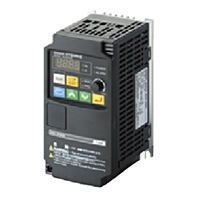
Easy-to-use Inverters for simple applications
* Information in this page is a reference that you created on the basis of information in the product catalog before the end of production, may be different from the current situation, such as goods for / supported standards options / price / features of the product. Before using, please check the compatibility and safety system.
Related Contents
- Features
- Lineup
- Specifications
- Dimensions
- Catalog / Manual / CAD / Software
last update: November 21, 2013
Performance Specifications
Inverter 3G3JX
3-phase 200-V Class
| Item | 3-phase 200-V class | ||||||||
|---|---|---|---|---|---|---|---|---|---|
| Model name (3G3JX-) | A2002 | A2004 | A2007 | A2015 | A2022 | A2037 | A2055 | A2075 | |
| Applicable motor
capacity *1 |
kW | 0.2 | 0.4 | 0.75 | 1.5 | 2.2 | 3.7 | 5.5 | 7.5 |
| HP | 1/4 | 1/2 | 1 | 2 | 3 | 5 | 7.5 | 10 | |
| Rated output
capacity (kVA) |
200V | 0.4 | 0.9 | 1.3 | 2.4 | 3.4 | 5.5 | 8.3 | 11.0 |
| 240V | 0.5 | 1.0 | 1.6 | 2.9 | 4.1 | 6.6 | 9.9 | 13.3 | |
| Rated input voltage | 3-phase (3-wire) 200 V -15% to 240 V +10%, 50/60 Hz ± 5% | ||||||||
| Built-in filter | Radio noise filter | ||||||||
| Rated input current (A) | 1.8 | 3.4 | 5.2 | 9.3 | 13.0 | 20.0 | 30.0 | 40.0 | |
| Rated output voltage *2 | 3-phase: 200 to 240 V (according to the input voltage) | ||||||||
| Rated output current (A) | 1.4 | 2.6 | 4.0 | 7.1 | 10.0 | 15.9 | 24.0 | 32.0 | |
| Weight (kg) | 0.8 | 0.9 | 1.1 | 2.2 | 2.4 | 2.4 | 4.2 | 4.2 | |
| Cooling method | Self-cooling | Forced-air-cooling | |||||||
| Braking torque | At short-time
deceleration *3 At capacitor feedback |
Approx. 50% | Approx. 20% to
40% |
Approx. 20% | |||||
| DC injection braking | Injection braking frequency/time, braking force variable, frequency control
available |
||||||||
3-phase 400-V Class
| Item | 3-phase 400-V class | |||||||
|---|---|---|---|---|---|---|---|---|
| Model name (3G3JX-) | A4004 | A4007 | A4015 | A4022 | A4037 | A4055 | A4075 | |
| Applicable motor
capacity *1 |
kW | 0.4 | 0.75 | 1.5 | 2.2 | 3.7 | 5.5 | 7.5 |
| HP | 1/2 | 1 | 2 | 3 | 5 | 7.5 | 10 | |
| Rated output
capacity (kVA) |
380V | 0.9 | 1.6 | 2.5 | 3.6 | 5.6 | 8.5 | 10.5 |
| 480V | 1.2 | 2.0 | 3.1 | 4.5 | 7.1 | 10.8 | 13.3 | |
| Rated input voltage | 3-phase (3-wire) 380 V -15% to 480 V +10%, 50/60 Hz ± 5% | |||||||
| Built-in filter | Radio noise filter | |||||||
| Rated input current (A) | 2.0 | 3.3 | 5.0 | 7.0 | 11.0 | 16.5 | 20.0 | |
| Rated output voltage *2 | 3-phase: 380 to 480 V (according to the input voltage) | |||||||
| Rated output current (A) | 1.5 | 2.5 | 3.8 | 5.5 | 8.6 | 13.0 | 16.0 | |
| Weight (kg) | 1.5 | 2.3 | 2.4 | 2.4 | 2.4 | 4.2 | 4.2 | |
| Cooling method | Self-cooling | Forced-air-cooling | ||||||
| Braking torque | At short-time
deceleration *3 At capacitor feedback |
Approx. 50% | Approx. 20% to 40% | Approx. 20% | ||||
| DC injection braking | Injection braking frequency/time, braking force variable, frequency control
available |
|||||||
1/3-phase 200-V Class
| Item | 1/3-phase 200-V Class | |||||
|---|---|---|---|---|---|---|
| Model name (3G3JX-) | AE002 | AE004 | AE007 | AE015 | AE022 | |
| Applicable motor
capacity *1 |
kW | 0.2 | 0.4 | 0.75 | 1.5 | 2.2 |
| HP | 1/4 | 1/2 | 1 | 2 | 3 | |
| Rated output
capacity (kVA) |
200V | 0.4 | 0.9 | 1.3 | 2.4 | 3.4 |
| 240V | 0.5 | 1.0 | 1.6 | 2.9 | 4.1 | |
| Rated input voltage | 1/3-phase 200 V -15% to 240 V +10%, 50/60 Hz ± 5% | |||||
| Built-in filter | None | |||||
| Rated input
current (A) |
1-phase | 3.1 | 5.8 | 9.0 | 16.0 | 22.5 |
| 3-phase | 1.8 | 3.4 | 5.2 | 9.3 | 13.0 | |
| Rated output voltage *2 | 3-phase: 200 to 240 V (according to the input voltage) | |||||
| Rated output current (A) | 1.4 | 2.6 | 4.0 | 7.1 | 10.0 | |
| Weight (kg) | 0.8 | 0.9 | 1.1 | 2.2 | 2.4 | |
| Cooling method | Self-cooling | Forced-air-cooling | ||||
| Braking torque | At short-time
deceleration *3 At capacitor feedback |
Approx. 50% | Approx. 20% to 40% | |||
| DC injection braking | Injection braking frequency/time, braking force variable, frequency control
available |
|||||
*1 The applicable motor is a 3-phase standard motor. For using any other type, be sure that the rated current does not
exceed that of the Inverter.
*2 Output voltage decreases according to the level of the power supply voltage.
*3 The braking torque at the time of capacitor feedback is an average deceleration torque at the shortest deceleration
(when it stops from 50 Hz), not a continuous regeneration torque. Also, the average deceleration torque varies
depending on the motor loss. The value is reduced in operation over 50 Hz. Note that no regenerative braking circuit is
built into the Inverter. If you need a larger regenerative torque, use the optionally available regenerative braking unit
and resistor.
The regenerative braking unit should be used only for short-time regeneration.
Function Specifications
Inverter 3G3JX
| Item | Specifications | |
|---|---|---|
| Enclosure rating *1 | Semi-closed (IP20) | |
| Control | Control method | Phase-to-phase sinusoidal modulation PWM |
| Output frequency range *2 | 0.5 to 400 Hz | |
| Frequency precision *3 | Digital command: ±0.01% of the max. frequency
Analog command: ±0.4% of the max. frequency (25 °C ±10 °C) |
|
| Frequency setting
resolution |
Digital setting: 0.1 Hz
Analog setting: Max. frequency/1000 |
|
| Voltage/Frequency
characteristics |
V/f characteristics (constant/reduced torque) | |
| Overload current rating | 150% for 1 min | |
| Acceleration/
Deceleration time |
0.01 to 3000 s (line/curve selection), 2nd acceleration/deceleration setting
available |
|
| Carrier frequency
modification range |
2 to 12 kHz | |
| DC injection braking | Starts at a frequency lower than that in deceleration via the STOP command,
at a value set lower than that during operation, or via an external input. (Level and time settable.) |
|
| Protective functions | Overcurrent, overvoltage, undervoltage, electronic thermal, temperature
error, ground-fault overcurrent at power-on state, overload limit, incoming overvoltage, external trip, memory error, CPU error, USP trip, communication error, overvoltage protection during deceleration, momentary power interruption protection, emergency shutoff |
|
| Input
signal |
Multi-function input | FW (forward), RV (reverse), CF1 to CF4 (multi-step speed), JG (jogging), DB
(external DC injection braking), SET (2nd function), 2CH (2-step acceleration/deceleration), FRS (free run), EXT (external trip), USP (USP function), SFT (soft lock), AT (analog current input function selection), RS (reset), PTC (thermistor input), STA (3-wire startup), STP (3-wire stop), F/R (3-wire forward/reverse), PID (PID selection), PIDC (PID integral reset), UP (UP of UP/DWN function), DWN (DWN of UP/DWN function), UDC (data clear of UP/DWN function), OPE (forced OPE mode), ADD (frequency addition), F-TM (forced terminal block), RDY (operation ready), SP-SET (special setting), EMR (emergency shutoff) |
| Output
signal |
Multi-function output | RUN (signal during operation), FA1 (frequency arrival signal 1), FA2 (frequency
arrival signal 2), OL (overload warning signal), OD (PID excess deviation signal), AL (alarm signal), DC (analog input disconnection detection signal), FBV (PID FB status output), NDc (network error), LOG (logical operation result), LOC (light load signal) |
| Frequency monitor | Analog output (0 to 10 V DC, 1 mA max.)
Frequency/Current signals are selectable via the AM output terminal. |
|
| Relay output | The relay (SPDT contact) outputs signals corresponding to the multi-
function output. |
|
| Other functions | AVR function, V/f characteristic selection, upper/lower limit, 16-step
speeds, starting frequency adjustment, jogging operation, carrier frequency adjustment, PID control, frequency jump, analog gain/bias adjustment, S- shape acceleration/deceleration, electronic thermal characteristics/level adjustment, retry function, simplified torque boost, trip monitor, soft lock function, frequency conversion display, USP function, 2nd control function, motor rotation speed UP/DOWN, overcurrent suppression function |
|
| General
specifi- cations |
Ambient temperature | -10 °C to 50 °C (Both the carrier frequency and output current need
to be reduced at over 40 °C.) |
| Ambient storage
temperature |
-20 °C to 65 °C (short-time temperature during transport) | |
| Humidity | 20% to 90% RH | |
| Vibration | 5.9 m/s2 (0.6G), 10 to 55 Hz (Complies with the test method specified in
JIS C0040 (1999).) |
|
| Location | At a maximum altitude of 1,000 m; indoors (without corrosive gases or dust) | |
| Applicable standard | Complies with UL, cUL, CE standards. (Insulation distance) | |
| Options | Noise filter, AC/DC reactors, regenerative braking unit and resistor, etc. | |
*1 Protection method complies with JEM 1030.
*2 To operate the motor at over 50/60 Hz, contact the motor manufacturer to find out the maximum allowable speed of
revolution.
*3 For the stable control of the motor, the output frequency may exceed the maximum frequency set in A004 (A204) by
2 Hz max.
*2 To operate the motor at over 50/60 Hz, contact the motor manufacturer to find out the maximum allowable speed of
revolution.
*3 For the stable control of the motor, the output frequency may exceed the maximum frequency set in A004 (A204) by
2 Hz max.
Options
Regenerative Braking Unit 3G3AX-RBU[][]
Built-in Resistance Type (3G3AX-RBU21/-RBU22/-RBU41)
| Class | 3-phase 200 V class | 3-phase 400 V class | ||
|---|---|---|---|---|
| Model name (3G3AX-) | RBU21 | RBU22 | RBU41 *1 | |
| Connection resistance | 17 Ω min. | 17 Ω min. | 34 Ω min. | |
| Operating voltage ON/OFF | ON: 362.5±5 V, OFF: 355±5 V
(-5% or -10% setting available) |
ON: 725±5 V,
OFF: 710±5 V (-5% or -10% setting available) |
||
| Operation indication | LED ON (Lit) | |||
| Maximum number of units for
parallel interlocking operation *2 |
5 units | |||
| Built-in
resistor |
Built-in resistance | 120 W 180 | 120 W 20 | 120 W 180 × 2 main
elements |
| Allowable consecutive
ON time |
10s max. | 0.5s max. | 10s max. | |
| Allowable operation
cycle |
Cycle 1/10
(10 s ON/90 s OFF) |
Cycle 1/80
(0.5 s ON/40 s OFF) |
Cycle 1/10
(10 s ON/90 s OFF) |
|
| Power consumption | Instantaneous: 0.73 kW
Short-time rating: 120 W |
Instantaneous: 6.6 kW
Short-time rating: 120 W |
Instantaneous: 1.46 kW
Short-time rating: 240 W |
|
| Protective
functions |
Built-in Resistor
Overheat protection |
Built-in relay specifications
The temperature relay operates if the built-in resistor reaches approx. 200 °C and recovers at approx. 170 °C max. Built-in temperature fuse (recovery impossible) *3 Contact rating 250 VAC 200 mA (R load) 12 VDC 500 mA (R load)j 42 VDC 200 mA (R road) Minimum load 1mA |
||
| Operating
environ- ment |
Ambient temperature | -10 to 50 °C | ||
| Ambient storage
temperature |
-20 °C to 65 °C (short-time temperature during transport) | |||
| Humidity | 20% to 90% (with no condensation) | |||
| Vibration | 5.9 m/s2 (0.6 G) 10 to 55 Hz | |||
| Location | At a maximum altitude of 1,000 m; indoors (without corrosive gases or dust) | |||
| Paint color | Munselle 5Y7/1 (cooling fan: aluminum color) | |||
*1 To use the Regenerative Braking Unit for 1.5 kW or more 200 V class or the 2.2 kW or more 400 V class, be sure to
remove the built-in resistor.
*2 Set the DIP switches.
*3 The built-in resistor incorporates a temperature fuse. If the alarm terminal is not connected, the fuse may blow out in
order to prevent the resistor burning due to overheating. If the fuse blows out, the built-in resistor must be replaced.
remove the built-in resistor.
*2 Set the DIP switches.
*3 The built-in resistor incorporates a temperature fuse. If the alarm terminal is not connected, the fuse may blow out in
order to prevent the resistor burning due to overheating. If the fuse blows out, the built-in resistor must be replaced.
Braking Resistor 3G3AX-RB[][][][][]
| Model | Compact type
(3G3AX-RBA[][][][]) |
Standard type
(3G3AX-RBB[][][][]) |
Medium capacity type
(3G3AX-RBC[][][][]) |
|||||||||
|---|---|---|---|---|---|---|---|---|---|---|---|---|
| 1201 | 1202 | 1203 | 1204 | 2001 | 2002 | 3001 | 4001 | 4001 | 6001 | 12001 | ||
| Resistance | Capacity | 120W | 120W | 120W | 120W | 200W | 200W | 300W | 400W | 400W | 600W | 1200W |
| Resistance (Ω) | 180 | 100 | 50 | 35 | 180 | 100 | 50 | 35 | 50 | 35 | 17 | |
| Allowable braking frequency
(%) |
5 | 2.5 | 1.5 | 1.0 | 10 | 7.5 | 7.5 | 7.5 | 10 | 10 | 10 | |
| Allowable continuous braking
time (s) |
20 | 12 | 5 | 3 | 30 | 30 | 30 | 20 | 10 | 10 | 10 | |
| Weight (kg) | 0.27 | 0.27 | 0.27 | 0.27 | 0.97 | 0.97 | 1.68 | 2.85 | 2.5 | 3.6 | 6.5 | |
| Fault detection function | Built-in thermal (contact capacity 240 VAC, 2 A max.,
minimum current 5 mA), Normally ON (NC contact) Built-in temperature fuse (non-recovery) |
Built-in temperature
relay, Normally ON (NC) Contact capacity: 240 VAC 3 A (R load), 0.2 A (L load), 36 VDC 2 A (R load) |
||||||||||
| General
specifi- cation |
Ambient
temperature |
-10 to 50 °C | ||||||||||
| Humidity | 20% to 90% (RH) with no condensation | |||||||||||
| Vibration | 5.9 m/s (0.6 G) 10 to 55 Hz Complies with JISC0911 | |||||||||||
| Location | At a maximum altitude of 1,000 m; indoors (without corrosive gases or dust) | |||||||||||
| Cooling method | Self-cooling | |||||||||||
Radio Noise Filter 3G3AX-ZCL[]
3G3AX-ZCL1
| Applicable
Inverter capacity (kW) |
200 V class | 400 V class | ||||||
|---|---|---|---|---|---|---|---|---|
| Input | Output | Input | Output | |||||
| No. of
filters |
No. of
penetrations |
No. of
filters |
No. of
penetrations |
No. of
filters |
No. of
penetrations |
No. of
filters |
No. of
penetrations |
|
| 0.2 | 1 | 4 | 1 | 4 | 1 | 4 | 1 | 4 |
| 0.4 | 1 | 4 | 1 | 4 | 1 | 4 | 1 | 4 |
| 0.75 | 1 | 4 | 1 | 4 | 1 | 4 | 1 | 4 |
| 1.5 | 1 | 4 | 1 | 4 | 1 | 4 | 1 | 4 |
| 2.2 | 1 | 4 | 1 | 4 | 1 | 4 | 1 | 4 |
| 3.7 | 1 | 4 | 1 | 4 | 1 | 4 | 1 | 4 |
| 5.5 | 1 | 4 | 1 | 4 | 1 | 4 | 1 | 4 |
| 7.5 | 1 | 4 | 1 | 4 | 1 | 4 | 1 | 4 |
3G3AX-ZCL2
| Applicable
Inverter capacity (kW) |
200 V class | 400 V class | ||||||
|---|---|---|---|---|---|---|---|---|
| Input | Output | Input | Output | |||||
| No. of
filters |
No. of
penetrations |
No. of
filters |
No. of
penetrations |
No. of
filters |
No. of
penetrations |
No. of
filters |
No. of
penetrations |
|
| 0.2 | 1 | 4 | 1 | 4 | 1 | 4 | 1 | 4 |
| 0.4 | 1 | 4 | 1 | 4 | 1 | 4 | 1 | 4 |
| 0.75 | 1 | 4 | 1 | 4 | 1 | 4 | 1 | 4 |
| 1.5 | 1 | 4 | 1 | 4 | 1 | 4 | 1 | 4 |
| 2.2 | 1 | 4 | 1 | 4 | 1 | 4 | 1 | 4 |
| 3.7 | 1 | 4 | 1 | 4 | 1 | 4 | 1 | 4 |
| 5.5 | N/A | N/A | 1 | 4 | 1 | 4 | ||
| 7.5 | 1 | 4 | 1 | 4 | ||||
Input Noise Filter 3G3AX-NFI[][]
| Power
supply |
Model | Applicable
Inverter capacity (kW) |
Rated input
current In (A) at an ambient temperature of 50 °C |
Pow-
er loss (W) |
Leakage
current (mA/ phase) at 60 Hz |
Case
enclosure rating |
Ter-
minal size |
Wire
dia. |
Weight
(kg) |
|---|---|---|---|---|---|---|---|---|---|
| 3-phase
200 VAC |
3G3AX-NFI21 | 0.2 to 0.75 | 3 × 6 A | 3 | <1.5 (250V) | Plastic, IP00 | M4 | 1.25mm2 | 0.5 |
| 3G3AX-NFI22 | 1.5 | 3 × 10 A | 4 | <1.5 (250V) | Plastic, IP00 | M4 | 2mm2 | 0.6 | |
| 3G3AX-NFI23 | 2.2, 3.7 | 3 × 20 A | 6 | <1.5 (250V) | Plastic, IP00 | M4 | 2mm2,
3.5mm2 |
0.7 | |
| 3G3AX-NFI24 | 5.5 | 3 × 30 A | 9 | <1.5 (250V) | Plastic, IP00 | M4 | 5.5mm2 | 0.8 | |
| 3G3AX-NFI25 | 7.5 | 3 × 40 A | 12 | <1.5 (250V) | Plastic, IP00 | M5 | 8mm2 | 1.4 | |
| 3-phase
400 VAC |
3G3AX-NFI41 | 0.4 to 2.2 | 3 × 7 A | 2 | <7.5 (480V) | Plastic, IP00 | M4 | 1.25mm2,
2mm2 |
0.7 |
| 3G3AX-NFI42 | 3.7 | 3 × 10 A | 4 | <7.5 (480V) | Plastic, IP00 | M4 | 2mm2 | 0.7 | |
| 3G3AX-NFI43 | 5.5, 7.5 | 3 × 20 A | 6 | <7.5 (480V) | Plastic, IP00 | M4 | 2mm2,
3.5mm2 |
0.7 |
EMC-compatible Noise Filter 3G3AX-EFI[][]
| Power
supply |
Model | Applicable Inverter capacity
(kW) |
Input
current In (A) |
Leakage
current (mA/ phase at 60 Hz) |
Case,
En- closure rating |
Screw
size |
Wire
size |
Weight
(kg) |
||
|---|---|---|---|---|---|---|---|---|---|---|
| 1-phase
200 V |
3-phase
200 V |
3-phase
400 V |
||||||||
| 1-phase
200 VAC |
3G3AX-
EFIB1 |
0.2, 0.4 | --- | --- | 2 × 6 A | 15 | Alumi-
num, IP20 |
M4 | 1.3mm2 | 0.43 |
| 3G3AX-
EFIB2 |
0.75 | --- | --- | 2 × 10 A | 15 | 2.1mm2 | 0.6 | |||
| 3G3AX-
EFIB3 |
1.5, 2.2 | --- | --- | 2 × 21 A | 15 | 3.3 to
5.3mm2 |
0.88 | |||
| 3-phase
200 VAC |
3G3AX-
EFI21 |
--- | 0.2, 0.4 | --- | 3 × 4 A | 15 | Alumi-
num, IP20 |
M4 | 1.3mm2 | 0.56 |
| 3G3AX-
EFI22 |
--- | 0.75 | 0.4 to 1.5 | 3 × 5.2 A | 16 | 1.3mm2 | 0.72 | |||
| 3G3AX-
EFI23 |
--- | 1.5, 2.2 | 2.2, 3.7 | 3 × 14 A | 16 | 2.1mm2 | 1.2 | |||
| 3G3AX-
EFI24 |
--- | 3.7 | --- | 3 × 22 A | 16 | 3.3mm2 | 1.3 | |||
| 3G3AX-
EFI25 |
--- | 5.5, 7.5 | 5.5, 7.5 | 3 × 40 A | 90 | M5 | 3.3 to
8.4mm2 |
2.4 | ||
| 3-phase
200/ 400 VAC |
3G3AX-
EFI41 |
--- | 0.4 , 0.75 | 0.4 to 2.2 | 3 × 7 A | 150 | Plastic,
IP00 |
M4 | 1.25mm2,
2mm2 |
0.7 |
| 3G3AX-
EFI42 |
--- | 1.5 | 3.7 | 3 × 10 A | 150 | 2mm2 | 0.7 | |||
| 3G3AX-
EFI43 |
--- | 2.2, 3.7 | 5.5, 7.5 | 3 × 20 A | 170 | M5 | 2mm2,
3.5mm2 |
1 | ||
| 3G3AX-
EFI44 |
--- | 5.5 | --- | 3 × 30 A | 170 | 5.5mm2 | 1.3 | |||
| 3G3AX-
EFI45 |
--- | 7.5 | --- | 3 × 40 A | 170 | 8mm2 | 1.4 | |||
Output Noise Filter 3G3AX-NFO[][]
| Power supply | Model | Rated current
(A) |
Applicable motor (kW) | External Dimensions
(H X W X D) (mm) |
Weight
(kg) |
|
|---|---|---|---|---|---|---|
| 200 V class | 400 V class | |||||
| 3-phase,3-wire
Rated voltage 500 VAC |
3G3AX-NFOO1 | 6 | to 0.75 | to 2.2 | 156 × 95 × 50 | 0.7 |
| 3G3AX-NFOO2 | 12 | 1.5, 2.2 | 3.7 | 176 × 110 × 70 | 0.9 | |
| 3G3AX-NFOO3 | 25 | 3.7, 5.5 | 5.5, 7.5 | 154 × 160 × 120 | 2.1 | |
| 3G3AX-NFOO4 | 50 | 7.5 | --- | 210 × 200 × 150 | 3.7 | |
DC Reactor 3G3AX-DL[][][][]
| Inverter Input
power supply |
Model | Applicable Inverter | Weight (kg) | Standard applicable wire |
|---|---|---|---|---|
| 3/1-phase
200 VAC |
3G3AX-DL2002 | 0.2 | 0.8 | 1.25 mm2 min. |
| 3G3AX-DL2004 | 0.4 | 1.0 | 1.25 mm2 min. | |
| 3G3AX-DL2007 | 0.75 | 1.3 | 2 mm2 min. | |
| 3G3AX-DL2015 | 1.5 | 1.6 | 2 mm2 min. | |
| 3G3AX-DL2022 | 2.2 | 2.1 | 2 mm2 min. | |
| 3G3AX-DL2037 | 3.7 | 2.6 | 3.5 mm2 min. | |
| 3G3AX-DL2055 | 5.5 | 3.6 | 8 mm2 min. | |
| 3G3AX-DL2075 | 7.5 | 3.9 | 14 mm2 min. | |
| 3-phase
400 VAC |
3G3AX-DL4004 | 0.4 | 0.8 | 1.25 mm2 min. |
| 3G3AX-DL4007 | 0.75 | 1.1 | 1.25 mm2 min. | |
| 3G3AX-DL4015 | 1.5 | 1.6 | 2 mm2 min. | |
| 3G3AX-DL4022 | 2.2 | 2.1 | 2 mm2 min. | |
| 3G3AX-DL4037 | 3.7 | 2.6 | 2 mm2 min. | |
| 3G3AX-DL4055 | 5.5 | 3.6 | 3.5 mm2 min. | |
| 3G3AX-DL4075 | 7.5 | 3.9 | 3.5 mm2 min. |
AC Reactor 3G3AX-AL[][][][]
| Power supply | Model | Applicable Inverter capacity (kw) | Weight (kg) |
|---|---|---|---|
| 3-phase
200 VAC |
3G3AX-AL2025 | 0.2 to 1.5 | 2.8 |
| 3G3AX-AL2055 | 2.2, 3.7 | 4.0 | |
| 3G3AX-AL2110 | 5.5, 7.5 | 5.0 | |
| 3-phase
400 VAC |
3G3AX-AL4025 | 0.4 to 1.5 | 2.7 |
| 3G3AX-AL4055 | 2.2, 3.7 | 4.0 | |
| 3G3AX-AL4110 | 5.5, 7.5 | 6.0 |
last update: November 21, 2013
 Product Category
- Motion / Drives
-
Inverters
-
Discontinued
- 3G3JX
-
Discontinued
-