CJ1W-CT021
CJ-series High-speed Counter Unit
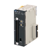
High-Speed, Flexible Control With A Wide Array of Features. This unit is available for CJ/NJ controller.
Related Contents
- Features
- Lineup
- Specifications
- Dimensions
- Catalog / Manual / CAD / Software
last update: April 1, 2021
General Specifications
| Item | CJ1W-CT021 |
|---|---|
| Unit type | CJ-series Special I/O Unit |
| General Specifications | Conform to general specifications for CJ/NJ-series |
| Ambient Operating Temperature | 0 to 55 °C |
| Ambient Storage Temperature | -20 to 75 °C |
| Ambient Operating Humidity | 10% to 90% without condensation |
| Internal Current Consumption | 280 mA (at 5 V) |
| Dimensions | 31 × 90 × 65 mm (W × H × D) |
| Weight | 100 g |
| Mounting Position | CJ-series CPU Rack or CJ-series Expansion Rack *1, NJ-series CPU Rack or NJ-series Expansion Rack |
| Maximum Number of CT021
Units per Rack |
Equal to the number of slots of the Rack *2 |
| Maximum Number of CT021
Units per basic CJ/NJ system |
24 |
| Data Exchange with CPU Unit | I/O Refresh Data Area (CIO-bits 200000 to 255915, CIO-words 2000 to 2959): *3
Special I/O Unit DM-Area (D-words 20000 to 29599): 400 DM-words per Unit are transmitted form the CPU to the Unit at Power Up or when the Unit is restarted *4 |
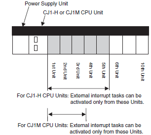
*1. The Unit must be in one of the five positions immediately to the right of the CJ1-H CPU Unit or in one of the three
positions immediately to the right of the CJ1M CPU Unit to activate external interrupt tasks. No external interrupt
tasks can be activated if the Unit is in any other position (i.e., 6th Unit position or further away from the CJ1-H CPU
Unit, or 4th Unit position or further away from the CJ1M CPU Unit), or if it is on a CJ-series Expansion Rack.
(Final order entry date for CJ1M:The end of March, 2021)
*2. The maximum number of Units per Rack is also depending on the maximum supply current of the Power Supply Unit
and the current consumption of other Units on the Rack.
*3. The CJ1W-CT021 Special I/O Unit is allocated words for 40 words in the Special I/O Unit (CIO) Area.
*4. The CJ1W-CT021 Special I/O Unit is allocated words for 4 Units in the Special I/O Unit DM Area. From the 400 DM
words that are allocated, the first 113 words are used to make the DM-settings and the remaining 287 words can be
used as work-words.
Functional Specifications
| Item | CJ1W-CT021 |
|---|---|
| Number of Counters | 2 |
| Counter Type | • Simple Counter
• Circular Counter • Linear Counter The Counter Type can be chosen by DIP switch at the front of the Unit. By default the Counters are set to Simple Counter. |
| Maximum Input
Frequency |
500 kHz |
| Maximum
Response Time |
0.5 ms |
| Signals per Counter | Phase A, B and Z |
| Digital I/O | •2 Digital Inputs (I0 and I1):
Every Digital Input can be assigned to a Counter. In this way one Counter can be controlled by a maximum of 2 Digital Inputs. •2 Digital Outputs (O0 and O1): The Unit Output Pattern represents the 2 Digital Outputs and 30 Soft Outputs. |
| Input Signal Types | • Phase Differential (multiplication ×1), (multiplication ×2) * 1 and (multiplication ×4) * 1
• Up/Down * 1 • Pulse & Direction * 1 |
| Counter Control using
CIO-software bits *4 |
• Open Gate / Start Counter: Counter is enabled to count pulses
• Close Gate / Stop Counter: Counter is disabled to count pulses • Preset Counter: Preset Value can be set in CIO • Reset Counter to zero • Capture Counter Value: Captured Counter Value can be read using IORDinstruction |
| Digital Input
Functionality |
• Gate * 1
• Reset * 1 • Preset * 1 • Capture * 1 • Stop/Capture-Continue * 1* 4 • Stop/Capture-Reset/Continue * 1* 4 • Capture/Reset * 1* 4 • Enable Reset * 1 • Disable Reset * 1 For every Function the corresponding action can be triggered on a rising- or on a falling edge. |
| Output Control Mode | • Automatic ON/OFF output according to the following three modes:
Range Mode * 1 Comparison Mode * 1 Rate Range * 1* 4 • Manual output control |
| Output State Control | On changing the Operating Mode of the controller from RUN/MONITOR → PROGRAM,
an I/O Bus Error or an Overflow/Underflow Error, the Digital Outputs can be configured to: • Continue automatic updating Output States • Freeze Output States * 1 • Predefine Output States * 1 |
| Output Driver
Configuration |
The Output Driver of every Digital Output can be configured as:
• NPN • PNP * 1 |
| Reset Signals | Every Counter can be reset to zero by (a combination of) the following sources:
• Software Counter Reset Bit • Digital Input * 1 • Z-Input * 1 |
| Extra Functions | • Programmable Output Pulse * 1:
To every Digital Output an ON-delay and/or a Pulse Duration [1 to 9999 ms] can be applied. • Rate Measurement * 1* 4: For every Counter the Pulse Rate can be measured by defining a Time-Window [1 to 9999 ms]. Up to a maximum of 64 Rate Values are stored in the Rate History Log File. Rate Values from the Rate History Log File can be read using the IORD-instruction. Additionally for every Counter two Rate Ranges can be defined that control the Outputs according to the measured Rate Value. • Hysteresis * 1: To prevent Outputs from being switched On and Off by very small fluctuations in the Counter Value around Range Limits, for every Counter an Hysteresis-value [1 to 255] can be defined (the Unit must in Range Mode). |
| Noise Filtering Counter
Inputs and Digital Inputs |
To suppress noise on the signal lines of the Counter Inputs (A and B) and the Digital Inputs
(I0 and I1) a Noise Filter can be configured: • 10 kHz * 1 • 50 kHz (default) • 500 kHz * 1 For the Digital Inputs the 500 kHz filter can not be selected. The Z-Input Signals of every Counter are filtered with a fixed Noise Filter of 1 kHz. |
| Initial Counter Value *4 | • The Initial Counter Value * 1 is transferred to the Unit when the Unit is Powered Up or Restarted.
The Initial Counter Value is very useful to overcome problems in case of power failure. |
| IORD- and
IOWR-instructions *4 |
Run-time * 3 configuration and operation of the High-speed Counter Unit is possible by using
IORD- and IOWR-instructions. The following data can be read or written: • DM-configuration data * 1 • Range- and Comparison Data * 1 • Captured Counter Value • Rate History Log File Data * 1 • Counter Value • (Re) Configure High-speed Counter Unit * 1 • Error Clear |
| Interrupts of Outputs *4 | • The Digital Outputs and the Soft Outputs of the Unit Output Pattern can all be configured to
generate interrupts to the CJ1-H/CJ1M CPU Unit * 1 * 2. |
| Interrupts of
Digital Inputs *4 |
• The Digital Inputs can all be configured to generate interrupts to the CJ1-H/ CJ1M CPU Unit * 2. |
| Error History
Log Function |
• Stores up to 30 error log records |
*1. This specification item is only supported for Circular and Linear Counters (not for Simple Counters). For a complete
overview of the differences between Simple and Circular/Linear Counters refer to High-speed Counter Unit Operation
Manual (Cat. No. W401).
*2. To activate external interrupt tasks, a CJ1-H or CJ1M CPU Unit must be used. CJ1 CPU Units do not support external
interrupt tasks. To activate external interrupt tasks in a CJ1-H CPU Unit, the CJ1W-CT021 High-speed Counter Unit
must be in one of the five positions immediately to the right of the CJ1-H CPU Unit. For CJ1M CPU Units, the CJ1W-
CT021 High-speed Counter Unit must be in one of the three positions immediately to the right of the CJ1M CPU Unit.
No external interrupt tasks can be activated if the Unit is in any other position (i.e., 6th Unit position or further away
from the CJ1-H CPU Unit, or 4th Unit position or further away from the CJ1M CPU Unit), or if it is on a CJseries
Expansion Rack. (Final order entry date for CJ1M:The end of March, 2021)
*3. If an IOWR- or IORD-instruction is used during operation, comparison will stop during instruction execution. Care
must be taken, therefore, with the timing of executing instructions.
*4. This specification item cannot be used with NJ-series CPU units.
must be taken, therefore, with the timing of executing instructions.
*4. This specification item cannot be used with NJ-series CPU units.
Input Specifications
| Item | Counter Inputs A and B | Digital Inputs
(I0 and I1) |
|||
|---|---|---|---|---|---|
| Input Voltage | 24 VDC
(19.6 to 26.4 V) |
12 VDC
(9.8 to 13.2 V) |
5 VDC
(4.5 to 5.5 V) |
Line Driver | 24 VDC
(19.6 to 26.4 V) |
| Input Current (typical) | 8 mA | 8 mA | 7 mA | 11 mA
Connectable to RS-422 compatible Line Drivers. |
7.6 mA |
| ON Voltage (min.) | 19.6 V | 9.8 V | 4.5 V | 19.6 V | |
| OFF Voltage (max.) | 4 V | 2.5 V | 1.5 V | 4 V | |
| Item | Counter Input Z | |||
|---|---|---|---|---|
| Input Voltage | 24 VDC (18.6 to 26.4 V) | 12 VDC (9.8 to 13.2 V) | 5 VDC (4.5 to 5.5 V) | Line Driver |
| Input Current (typical) | 7.3 mA | 6.6mA | 6 mA | 11 mA
Connectable to RS-422 compatible Line Drivers. |
| ON Voltage (min.) | 18.6 V | 9.8V | 4.5 V | |
| OFF Voltage (max.) | 4 V | 2.5V | 1.5 V | |
Note: 1. The Counter Inputs (A, B, Z) are insulated from each other and from the Digital Inputs. The Digital Inputs are also
insulated from each other. All Counter Inputs and Digital Inputs are reverse polarity protected and insulated from
the I/O-bus.
2. A noise filter can be configured (10 kHz or 50 kHz (default)) for the Digital Inputs. Every Z-Input has a defined
noise filter of 1 kHz.
3. If the 50-kHz noise filter is configured for External Control Inputs, signals of 10 μs or longer can be read.
| Counter Inputs A, B, Z and Digital Inputs | |
|---|---|
| 5/12/24V input signals | RS-422 Line Driver signals |
| Counter inputs A and B
Input pulses with a duty factor of 50% 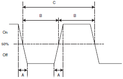
Relationship between A and B phases with phase differential inputs 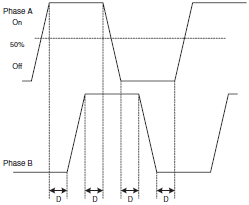
Counter Input Z */Digital Inputs (24 V) 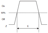
*Maximum allowed frequency of Z-pulses is 1 kHz |
Counter inputs A and B
Input pulses with a duty factor of 50% 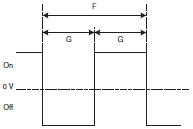
Relationship between A and B phases with phase differential inputs 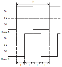
Counter Input Z * 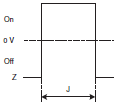
* Maximum allowed frequency of Z-pulses is 1 kHz |
| Filter Selection | Timing requirement (μs) | |||||||||
|---|---|---|---|---|---|---|---|---|---|---|
| A | B | C | D | E | F | G | H | I | J | |
| 10 kHz | <3 | >50 | >100 | >23 | >10 | >100 | >50 | >100 | >23 | >10 |
| 50 kHz | <3 | >10 | >20 | >4.5 | >10 | >20 | >10 | >20 | >4.5 | >10 |
| 500 kHz | - | - | - | - | - | >2 | >1 | >4 | >1 | >10 |
Note: As a general guideline it can be stated that if you want the timing requirements for the Counter Inputs to satisfy the
above mentioned specifications, you must pay attention to the type of output driver of the encoder being used, the
length of the encoder cable and the frequency of the count pulses generated. For example, if you use an Open
Collector encoder (e.g. E6B2-CWZ6C) at 24 V with 10 m cable, you can typically generate count pulses up to 20 kHz.
Therefore, if you want to generate count pulses with higher frequencies, you should use a different type of encoder
(e.g. E6B2-CWZ1X with Line Driver output or a fast push-pull 24 V encoder, e.g. E6C3-CWZ5GH (Complementary
output)) or reduce the length of the encoder cable.
Output Specifications
| Item | Specification |
|---|---|
| Driver Type | Open Collector (NPN/PNP selectable) |
| Operating Voltage Range | 12 to 24 V (10.2 to 26.4 V) 30 mA max. at 26.4 VDC (for PNP output, without load current) |
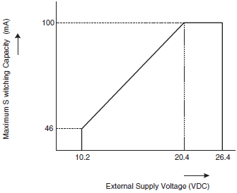
| Maximum Switching Capacity | 46 mA at 10.2 V to 100 mA at 26.4 V (200 mA maximum/common) (see picture below) |
| Minimum Switching Current | 5 mA |
| Output ON-delay | 100 μs max. |
| Output OFF-delay | 100 μs max. |
| Leakage Current | 0.1 mA max. |
| Residual Voltage | 1.5 V max. |
| Short Circuit Protection | No |
Note: 1. Every Digital Output has 2 Output drivers available: NPN and PNP (available as separate pins on the front
connectors). Every Output can be separately (DM-) configured for NPN or PNP. By default the Outputs are
configured as NPN-output.
2. The Digital Outputs are insulated from the I/O-bus but not from each other. They are not short circuit protected.
3. The Output current must not exceed 200 mA per common (i.e. per 2 Digital Outputs) otherwise the unit will be
damaged.
4. The Outputs can be automatically or manually controlled (DM-setting) by using Manual Output Control in CIO.
5. The state control of the Outputs, in case the operating mode of the CPU-Unit is changed from RUN/MONITOR →
PROGRAM, an I/O Bus error or an Overflow/Underflow error occurs, can be configured.
Maximum Switching Capacity
The maximum switching current depends upon the power supply voltage, as shown below.
last update: April 1, 2021