Discontinued On Mar. 2019
E5ZN
Modular Temperature Controller
New DIN Track Mounting Temperature Controller
* Information in this page is a reference that you created on the basis of information in the product catalog before the end of production, may be different from the current situation, such as goods for / supported standards options / price / features of the product. Before using, please check the compatibility and safety system.
Related Contents
- Features
- Lineup
- Specifications
- Dimensions
- Catalog / Manual / CAD / Software
last update: April 3, 2017
Ratings
| Power supply voltage | 24 VDC | ||
|---|---|---|---|
| Allowable voltage range | 85% to 110% of the rated power supply voltage | ||
| Power consumption | Approx. 3 W | ||
| Sensor input | Thermocouple: K, J, T, E, L, U, N, R, S, B
Infrared temperature sensor (ES1B series): 10 to 70°C, 60 to 120°C, 115 to 165°C, 140 to 260°C Voltage input: 0 to 50 mV |
||
| Platinum resistance thermometer: Pt100, JPt100 | |||
| Control output | Voltage output
(for driving SSR) |
Output voltage: 12 VDC ±15% (PNP);
Maximum load current: 21 mA; Equipped with short-circuit protection circuit |
|
| Transistor output | Maximum operational voltage: 30 VDC;
Maximum load current: 100 mA; Residual voltage: 1.5 V max.; Leakage current: 0.4 mA max. |
||
| Current output | Current output range: 4 to 20/0 to 20 mA DC;
Load: 350 Ω max. (See note 2.) |
||
| Auxiliary output | Transistor output | Sourcing | Maximum operating voltage: 30 VDC;
Maximum load current: 50 mA; Residual voltage: 1.5 V max.; Leakage current: 0.4 mA max. |
| Sinking | |||
| Linear voltage output | Voltage output range: 1 to 5/0 to 5 VDC;
Load: 10 kΩ min. |
||
| Event input | Contact output | ON: 1 kΩ max., OFF: 100 kΩ min.
Discharge current: Approx. 7 mA |
|
| Non-contact
output |
ON: Residual voltage: 1.5 V max., OFF: Leakage current: 0.1 mA max.
Discharge current: Approx. 7 mA |
||
| Number of input and
control points |
Input points: 2, Control points: 2 | ||
| Setting method | Via communications or using the Setting Display Unit (E5ZN-SDL *) | ||
| Control method | 2-PID or ON/OFF control | ||
| Other functions | Heater burnout detection function, transfer output function
Multi-SP and RUN/STOP switching using event input |
||
| Ambient operating
temperature |
-10 to 55℃ (with no icing or condensation)
For 3 years of assured use: -10 to 50℃ |
||
| Ambient operating
humidity |
25% to 85% | ||
| Storage temperature | -25 to 65℃ (with no icing or condensation) | ||
* Production was discontinued.
Note: 1. Do not use an inverter output for the power supply. (Refer to Safety Precautions for All Temperature Controllers.)
2. OMRON G32A-EA Cycle Controller Unit (load impedance 352 Ω) can be used.
Note: 1. Do not use an inverter output for the power supply. (Refer to Safety Precautions for All Temperature Controllers.)
2. OMRON G32A-EA Cycle Controller Unit (load impedance 352 Ω) can be used.
Input Range
Platinum Resistance Thermometer Models and Thermocouple Models
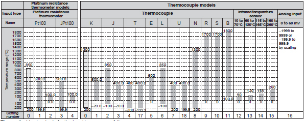
The applicable standards for the input types are as follows:
• K, J, T, E, N, R, S, B: JIS C1602-1995, IEC584-1
• L: Fe-CuNi, DIN 43710-1985
• U: Cu-CuNi, DIN 43710-1985
• JPt100: JIS C 1604-1989, JIS C 1606-1989
• Pt100: JIS C 1604-1997 IEC 751
Shaded parts indicate the settings at the time of purchase.
Characteristics
| Indication accuracy | Thermocouple: (Indicated value ±0.5% or ±1℃, whichever is greater) ±1 digit max. *1
Platinum resistance thermometer: (Indicated value ±0.5% or ±1℃, whichever is greater) ±1 digit max. *1 Analog input: ±0.5% or ±1 digit max. CT input: ±5% FS ±1 digit max. |
|---|---|
| Influence of
temperature |
Thermocouple input (R, S, B): (±1% of PV or ±10℃, whichever is greater) ±1 digit max.
Other thermocouple input: ( ±1% of PV or ±4℃, whichever is greater) ±1 digit max. *K thermocouple at -100℃ max.: ±10℃ max. Platinum resistance thermometer: (±1% of PV or ±2℃, whichever is greater) ±1 digit max. Analog input: (±1%FS) ±1 digit max. |
| Influence of voltage | |
| Transfer output | Accuracy: ±0.5% FS *2 |
| Hysteresis | 0.1 to 999.9 EU (in units of 0.1 EU) *3 |
| Proportional band (P) | 0.1 to 999.9 EU (in units of 0.1 EU) *3 |
| Integral time (I) | 0 to 3,999 s (in units of 1 s) |
| Derivative time (D) | 0 to 3,999 s (in units of 1 s) |
| Control period | 1 to 99 s (in units of 1 s) |
| Manual reset value | 0.0 to 100.0% (in units of 0.1%) |
| Alarm setting range | -1,999 to 9,999 (Position of decimal point depends on input type.) |
| Sampling period | 500 ms |
| Insulation resistance | 20 MΩ min. (at 500 VDC) |
| Dielectric strength | 600 VAC for 1 minute at 50 or 60 Hz (between unlike terminals of charged parts) |
| Vibration resistance | 10 to 55 Hz, 10 m/s2 for 2 h each in X, Y, and Z directions |
| Shock resistance | 150 m/s2 max., 3 times each in ±X, ±Y, and ±Z directions |
| Weight | Temperature Controller: Approx. 90 g
Terminal Unit (18): Approx. 80 g Terminal Unit (24): Approx. 100 g |
| Degree of protection | Temperature Controller: IP00
Terminal Unit: IP00 |
| Memory protection | EEPROM (non-volatile memory) (Number of write operations: 100,000) |
| Approved standards
*4 |
UL File No.: E200593
CSA File No.: 203889-1140084 CE EMS: ESD EN61326, EN61000-4-2 (4 kV/contact, 8 kV/air) REM field EN61326, EN61000-4-3 (10 V/m) Fast transient EN61326, EN61000-4-4 (2 kV/DC power, 1 kV/I/O) Surge immunity EN61326, EN61000-4-5 (line to ground: 2 kV/DC power 1 kV/I/O, line to line: 1 kV/DC power) Conducted RF EN61326, EN61000-4-6 (10 V) EMI: Radiated EN61326 Class A |
*1. The indication accuracy for T and N thermocouples at −100°C, and for U and L thermocouples is ±2°C ±1 digit max.
There is no specification for the indication accuracy for the B thermocouple used at 400°C max. The indication
accuracy for R and S thermocouples at 200°C max. is ±3°C ±1 digit max.
*2. The transfer output accuracy for 0 to 4 mA when 0 to 20 mA DC is selected is ±0.5% FS +0.7 mA. The transfer output
accuracy for 0 to 1 V when 0 to 5 VDC is selected is ±0.5% FS +0.175 V.
*3. "EU" stands for "Engineering Unit."
*4. In order to satisfy the EN61326 Class A standard for conducted emissions, install a noise filter (Densei-Lambda MXB-
1206-33 or equivalent) in a DC power line as close to the E5ZN as possible.
Communications (Host Communications)
| Transmission line connection method | RS-485 multipoint |
|---|---|
| Communications method | RS-485 (2-wire, half-duplex) |
| Synchronization method | Start-stop synchronization |
| Baud rate | 4,800, 9,600, 19,200, or 38,400 bps |
| Transmission code | ASCII |
| Data bit length * | 7 or 8 bits |
| Stop bit length * | 1 or 2 bits |
| Error detection | Vertical parity (none, even, odd) |
| BCC (block check character) | |
| Flow control | None |
| Interface | RS-485 |
| Retry function | None |
| Number of Units that can be connected in parallel | 16 Units max. (32 channels) |
* The baud rate, data bit length, stop bit length, and vertical parity can all be set independently as host communications
settings.
: Default setting values
settings.
: Default setting values
Current Transformer (CT) (Order Separately)
| Dielectric strength | 1,000 VAC (1 minute) |
|---|---|
| Vibration resistance | 50 Hz, 98 m/s2 |
| Weight | E54-CT1: Approx. 11.5 g E54-CT3: Approx. 50 g |
| Accessories (E54-CT3 only) | Armature (2) Plug (2) |
Heater Burnout Alarm
| Maximum heater current | Single-phase, 50 A AC *1 |
|---|---|
| Input current readout accuracy | ±5% FS ±1 digit max. |
| Heater burnout alarm setting range | 0.0 to 50.0 A (in units of 0.1 A) *2 |
| Minimum detection ON time | 190 ms *3 |
*1. Use the K8AC-H Digital Heater Burnout Alarm Detector for burnout detection of 3-phase heaters.
*2. If the heater burnout alarm setting is set to 0.0 A, the alarm is always OFF, and if it is set to 50.0 A the alarm is
always ON.
*3. If the ON time for control output is less than 190 ms, heater burnout detection and heater current measurement will
not be performed.
*2. If the heater burnout alarm setting is set to 0.0 A, the alarm is always OFF, and if it is set to 50.0 A the alarm is
always ON.
*3. If the ON time for control output is less than 190 ms, heater burnout detection and heater current measurement will
not be performed.
Setting Display Unit (Order Separately)
| Power supply voltage | 24 VDC |
|---|---|
| Allowable voltage range | 85% to 110% of the rated power supply voltage |
| Power consumption | Approx. 1 W |
| Display method | 7-segment digital display and single-color display |
| Ambient operating temperature | -10 to 55 ℃ (with no icing or condensation)
For 3 years of assured use: -10 to 50 ℃ |
| Ambient operating humidity | 25% to 85% |
| Storage temperature | -25 to 65 ℃ (with no icing or condensation) |
| Communications method | RS-485 (half-duplex) |
| Communications format | Special protocol |
| Insulation resistance | 20 MΩ min. (at 500 VDC) |
| Dielectric strength | 1,500 VAC for 1 minute at 50 or 60 Hz (between unlike terminals of charged parts) |
| Vibration resistance | 10 to 55 Hz, 20 m/s2 for 2 h each in X, Y, and Z directions |
| Shock resistance | 300 m/s2 max., 3 times each in ±X, ±Y, and ±Z directions |
| Enclosure ratings | Front panel: IP50
Rear case: IP20 Terminal case: IP00 |
| Memory protection | EEPROM (non-volatile memory) (Number of writes: 100,000) |
| Weight | Approx. 100 g
Mounting bracket: Approx. 10 g |
last update: April 3, 2017
 Product Category
- Control Components
-
Temperature Controllers
-
Discontinued
- E5ZN
-
Discontinued
-